Correct Reservoir Design Air bubbles in hydraulic fluid first originate is in the reservoir. Hydraulic reservoir accessories or hydraulic tank accessories can play a significant role in how well a hydraulic reservoir performs and to what degree fluid cleanliness is maintained.
Solutions For Reservoir Design Power Motion
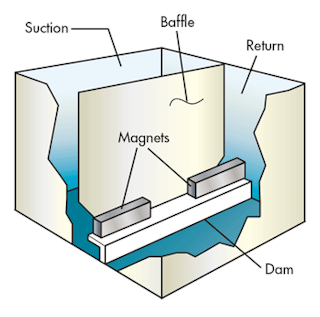
Baffles direct diffuse and contain fluid and increase tank stiffness Fig.

. Hydraulic Tank Baffle Design natebott Mechanical OP 2 May 06 1521. On the one hand a small oil volume results in lower total cost of ownership which gets more. October 20 2014 By Josh Cosford.
Index Termsroad tanker computer modeling liquid oscillations equivalent models baffles energy dissipation. DESIGN REQUIREMENTS FOR MAINTENANCE AND ACCESS a. In the design in Figure 6-5 the clean-out covers and internal baffle are assembled together with some brackets to keep the baffle upright.
Increasing the size or number of baffles beyond this point does little to increase the effectiveness of the mixing. The article provides a concise account of the constructional details of hydraulic reservoirs. Hydraulic Design Section of the Structural Branch in the Engineering Division of Civil Works.
A good hydraulic reservoir should have internal baffles situated in such a way that they prevent return line air. A complete range of 36 textbooks in Paperback Kindle eBooks Editions on Pneumatics and Hydraulics under Fluid Power Educational Series authored by Joji Parambath has. He was responsible for the final review of the hydraulic design of the Corps water resources projects and for the development and coordination of hydraulic research programs that supported hydraulic design.
The challenges of mobile reservoir design. Request PDF Hydraulic design of baffles in disinfection contact tanks This study focuses on understanding the hydraulic design of baffled contact tanks using computational fluid. Number of Baffles and Baffle Width.
Manholes 1 Spacing Where the proposed conduit is 60 and larger manholes should be spaced. Never rework a fuel tank into a hydraulic tank. To help cool return fluid it should be.
Return flow should never be aimed at a fluid intake line. Such designed solutions are baffles. The optimal baffle design determined based on an analysis of energy dissipation in a single cycle of oscillations is presented.
BAFFLE DESIGN Baffles direct diffuse and contain fluid and increase tank stiffness. Figure 1 To help cool return fluid it should be directed toward the outer walls of the reservoir. In the context of the design of a hydraulic tank there are different incentives to design the oil tank as small as possible.
The default number of baffles is four 4. A correctly designed reservoir tank will prevent this issue. A model of a thermal storage tank in which stored energy is extracted via an immersed heat exchanger is presented and used to predict transient temperature and velocity fields in tanks with and without baffles.
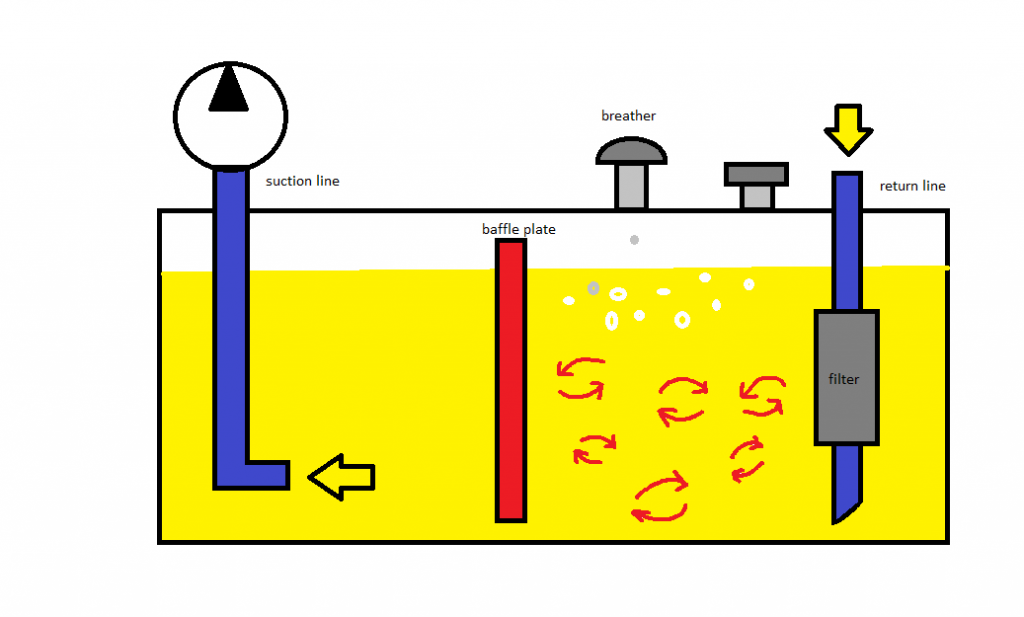
Hydraulic oil spends most of its time in the reservoir and as such various tank design criteria provide benefits for the hydraulic system as a whole. New oil being introduced into the reservoir can cause turbulent flow stirring up the oil and introducing air into the fluid which can lead to cavitation. Locate the inlet tube under a substantial depth of oil to avoid vortexes or add vanes to the throat of the tube extending outward.
Company standard which has been around for years states that oil passage cutouts have an area at least 2-12 times the total pump inlet area No one can tell me where this requirement came from. VALEW 2000 GALLON HYDRAULIC-DRIVE READY TANK KIT. Looking for rules of thumb on baffle design for hydraulic tanks.
By Gary Alexander CFPHS. Power response and flow response is always carried out in a vessel that has four standard width baffles width 112th of the tank diameter. VALEW 2000 GALLON HYDRAULIC-DRIVE READY TANK KIT SKU.
Hydraulic System Design Operation. Hydraulic flocculators have been used for water treatment in many countries with design based on the intensity of energy dissipation in the system usually related to ensuring that a particular value of average shear rate or velocity gradient G or the product of velocity gradient and retention time Gt is attained Fair and Geyer 1954 MacDonald and. The heat exchanger is modeled as a porous medium within the storage fluid.
If the system is badly contaminated it is wise to flush all pipes and actuators while changing the tank fluid. This allows more heat to radiate as it takes a longer route in the tank. Movement of tanks under braking are explained.
Web Design Los Angeles. The reservoir should have internal baffles to reduce sloshing and to prevent the hot returning oil from immediately entering the pumps intake port. The standard baffle design parameters are as follows.
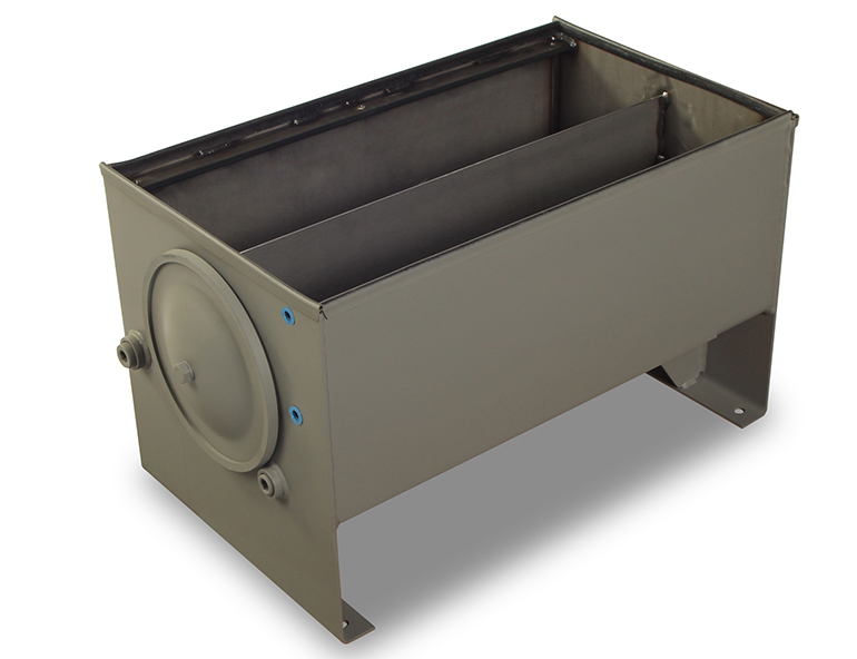
The fluid should also flow across magnets provided to intercept ferrous particles. Valew tank constructed from Domex Steel with internal baffles and horizontal bracing welded in accordance with ATSM welding practices. SSCAFCA DPM Section 3 HYDRAULIC DESIGN 22-122 Where conduits are to be decreased in size due to a change in grade the criteria for locating the transition will be as shown on Plate 223 B-4.
When designing the optimum hydraulic reservoir most of the considerations are in keeping the oil clean and cool. As you are aware a hydraulic reservoir is an essential part of a hydraulic power pack. Baffle Off Wall Dimension.
Standard baffle configuration utilises 3 or 4 equally spaced vertical baffles T12 where T is the internal tank diameter. Rubber gaskets seal the clean-out covers to prevent leaks.

Novel Slot Baffle Design To Improve Mixing Efficiency And Reduce Cost Of Disinfection In Drinking Water Treatment Journal Of Environmental Engineering Vol 143 No 9
Taking A Deep Dive Into The Hydraulic Reservoir

Industrial Hydraulics Design Hydraulic Reservoir Design

Fundamentals Of Hydraulic Reservoirs Power Motion
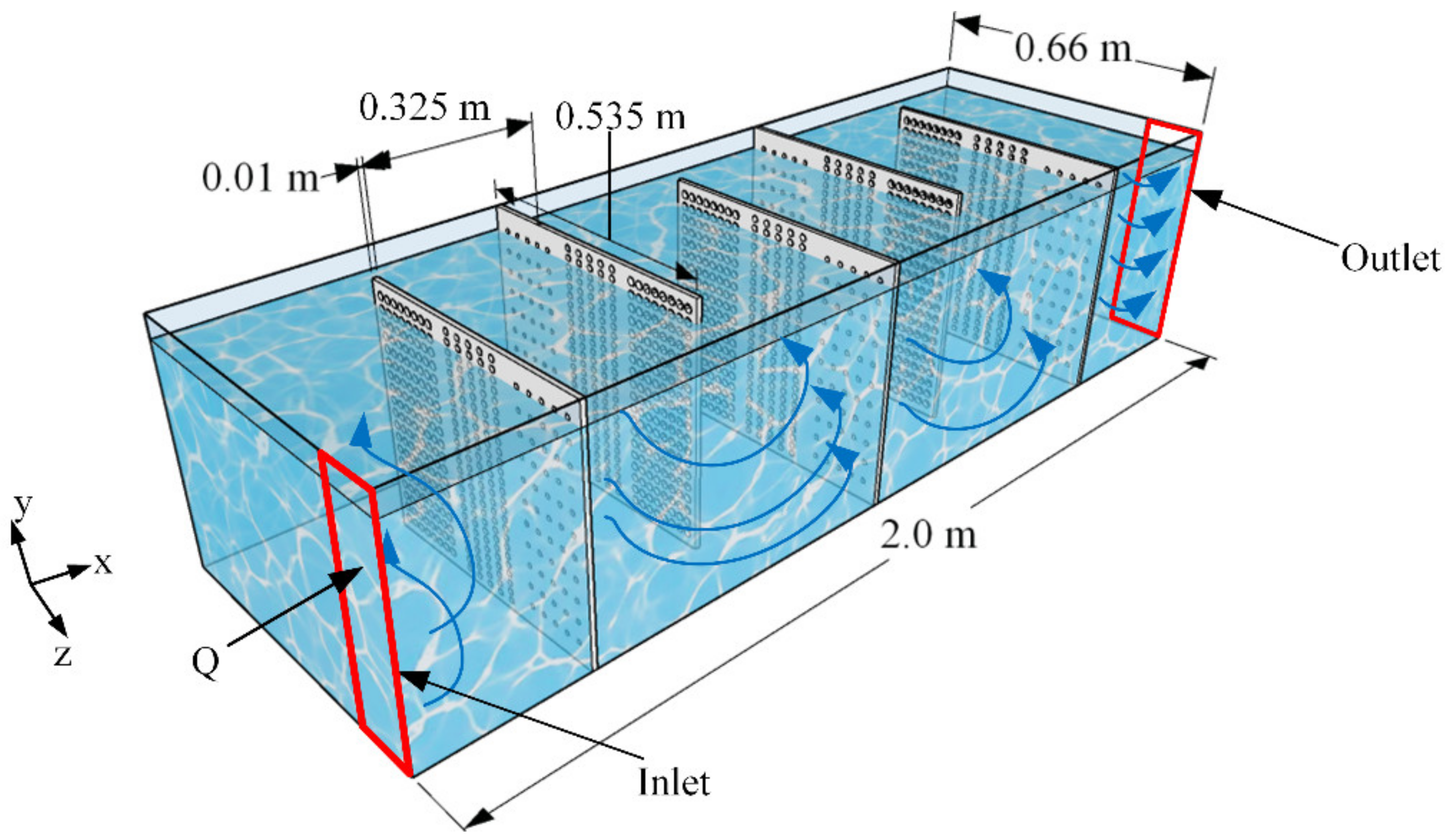
Water Free Full Text A Perforated Baffle Design To Improve Mixing In Contact Tanks

Why The Tank May Well Be A Hydraulic Fluid S Best Friend
Hydraulic Tank Design And Work Basic Stuffworking Com
Hydraulic Reservoirs Fluidsys Training Centre
0 comments
Post a Comment